With the increasing number of cars in China, the current traffic light mode uses timing control, because the traffic volume is changing at any time. When there is no car passing at this time, the opposite car has to wait until the green light in this direction ends to show the red light to pass, and the strain performance in time and space is poor, which not only wastes time, but also causes the traffic in the opposite direction to cause traffic jam. "phenomenon. In order to solve the "big traffic jam" phenomenon in the city, it is necessary to improve the original traffic light control system.
Therefore, based on the EDA technology, this paper designs the traffic light control system based on the relevant knowledge of FPGA. The lighting time can be adjusted freely according to the actual situation. The whole design system is simulated by Max+PlusII software and downloaded to the FPGA device. The hardware debugging is carried out to verify that the designed traffic signal control circuit can fully realize the predetermined function and has certain practicability.
1, system design requirements
The designed traffic signal control circuit is mainly suitable for the intersection formed at the junction of two main roads. The intersection design two sets of traffic lights to manage the traffic operation status in two directions. The continuous flashing time of the traffic light is controlled by the keyboard input. The light-on timing is shown in Figure 1. When the red light in the B direction is on, the green light in the A direction is bright, and the yellow light is turned in the transition phase from the green light to the red light, that is, the red light in the B direction is equal to the green light in the A direction and the yellow light. The sum of time. Similarly, when the red light in the A direction is bright, the traffic light in the B direction also follows this rule. A digital tube is installed on each main road to display the flashing time of each signal light in the countdown form. When a special situation occurs, all parties turn red and the countdown stops. After the special running state is over, the controller returns to its original state and continues to run.

Figure 1 Traffic light flashing timing diagram
2, the overall design of the system
The whole system design is shown in Figure 2. The system is mainly composed of a counting module, a control module, a frequency dividing module, a dividing module and a display circuit. The frequency dividing module mainly converts the reference clock signal input by the system into an excitation signal of 1 Hz, and drives the counting module and the control module to work. The control module controls the lighting and the duration of the traffic light according to the counting condition of the counter, and displays the light-on time in the form of a countdown through the digital tube through the dividing circuit. In the figure, Reset is a reset signal, and it is active high, which can realize asynchronous reset of the counter. Hold is the hold signal. When Hold is "1", the counter pauses counting, indicating that a special situation occurs and the vehicle is in the forbidden state in all directions.
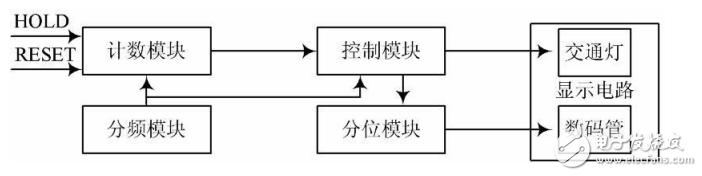
Figure 2 Traffic light control system module diagram
3. Main function module design and simulation
3.1, counting module design
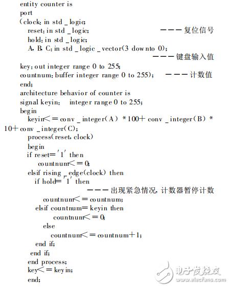
The counting module mainly implements the accumulating cycle counting. The maximum value of the counting is controlled by the keyboard input. The output counting value is a reference for the lighting control of the control module. The main program design of the counter is as follows:
The simulation of the counting module is shown in Fig. 3. As can be seen from the figure, under the driving of the clock, the counting value is continuously added. When the counting value countnum is equal to the keyboard input value 32 (key=32), the counting returns to 0. Start the next round of counting. Set a '1' when Hold detects a special condition, causing the counter to pause counting.
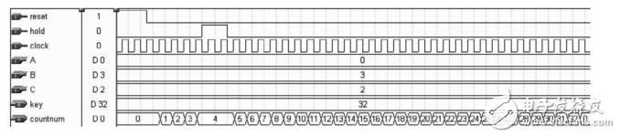
Figure 3 counting module simulation diagram
3.2. Simulation design of controller module
In the controller module, the total time of operation of the red, green and yellow lights is input by the keyboard. The time allocation rules of each traffic light are as follows: red light time accounts for 1/2 of the total time, green light time accounts for 3/8, yellow light The time is 1/8. In this design, the keyboard input value is 32 (key=32). Under normal circumstances, the red light is on for 16s, the green light is on 12s, and the yellow light is on 4s.
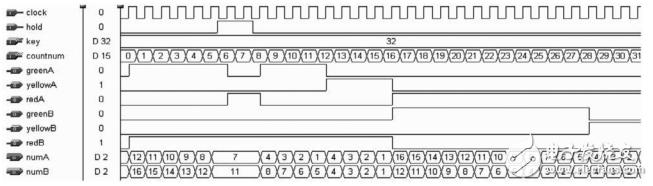
Figure 4 Control module simulation diagram
The simulation of the controller is shown in Figure 4. When the hold is low, the count value countnum "12, greenA outputs a high level, and the green light from the east-west direction lights up the vehicle. At this time, the corresponding redB output is high. Flat, the red light in direction B lights up and the vehicle is banned. The digital tube numA showing the duration of the traffic light blinking in the A direction is decremented from 12, and the digital tube numB showing the duration of the traffic light blinking in the B direction is decremented from 16. When 12 "countnum" 16 hours, yellowA output high level, A direction yellow light, numA countdown from value 4, greenB is still low, numB continues to count down, B direction red light flashing vehicle is still banned Line status. When countnum "16, redA output high level, A direction red light is on, the vehicle is forbidden, numA counts down from value 16. At this time, greenB outputs high level, B direction green light lights up the vehicle, numB starts to decrease from value 12. . When 16 "countnum" 28, redA continues to be in a high state, numA continues to count down, the A direction vehicle is forbidden, and at this time yellowB output is high, B direction yellow light is on, numB is decremented from the value 4. When the hold is `1', it means that it enters an emergency state, FLASH is set to `1', the red lights in all directions are on, and all motor vehicles are prohibited.
3.3, the design of the division module
The design of the grading module is mainly to divide the lighting time into ten digits and one digit, which are respectively displayed by two corresponding digital tubes. In this design, the light up time is no longer than 40s (numin "40", numA, numB respectively represent the number in ten digits and one digit, and the flowchart of the programming of the partition module is shown in Figure 5.
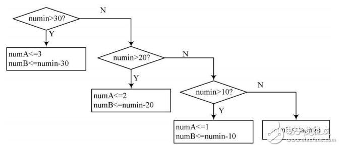
Figure 5 quantile module programming flow chart
The simulation of the quantile module is shown in Figure 6. The numerical value of numin can be displayed in decimal values ​​by the combination of numA and numB, thus realizing the quantile function.
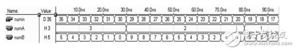
Figure 6 quantizer simulation
4, system hardware design and debugging
The main logic design of this system is completed by a piece of EP1K30TC144-3 chip. The VHDL source program is compiled and functionally simulated by Altera's logic synthesis tool Max+PlusII. The pin configuration for the download chip is downloaded to EP1K30TC144- In the 3 chips, the corresponding hardware debugging is performed, and the debugging results are consistent with the results of the software simulation, which verifies that the design has completed the predetermined function.
5 Conclusion
This paper uses hardware description language VHDL programming, compiled and simulated by Altera's Max+PlusII software environment, and realized a practical traffic signal control system through FPGA chip. The design uses EDA technology, which not only greatly shortens the development. The development cycle improves the design efficiency, and the system has the characteristics of flexible design, simple implementation and stable performance.
The Rock look porcelain tiles is manufactured with 3D printing technology to imitate the look of natual rock. Matte and rough surface available offer customer R10-R12 antiskid coefficient to make sure that the ceramic tiles are used in the wet place like bathroom,supermarket floor and other commericial area.

- Extraordinary durablity and simple maintenance.
- Scratch-resistance and waterproof.
- Stain-proof and less than 0.5% lower water absorption.
Rock Look Porcelain Tiles,Slip Resistance Floor Tile,Bathroom Floor Tile,Kitchen Ceramic Tile
Foshan Castel IMP&EXP Co.,Ltd , https://www.fscastel.com